Gas Production Mechanisms
The relevant laws of physics have not changed since those early days in the nascent electric power industry. For transformer manufacturers, the primary way to gain a competitive edge in the market has been through advancements in materials engineering and improved accuracy in the calculations used to predict their expected behaviour. Over the years, manufacturers and academic researchers have developed and commercialised new materials for each major transformer component and insulating liquids are no exception.
Mineral oil was the first liquid to be used for this purpose and it remains as the most popular option to fill liquid immersed transformers.
Progressively, other types of liquids have been developed and commercialised. Some were introduced and then removed from the market due to health, safety and environmental concerns, like the liquids containing an organic compound known as polychlorinated biphenyl (PCB).
Others, like the liquids based on oils extracted from plants and vegetables (esters) are currently trying to find their way into mainstream use by highlighting their biodegradability and higher flash point.
Since mineral oil is the most commonly used fluid in the industry, we will focus on this type of fluid for our discussion in this chapter.
Mineral oil
Crude oil undergoes various refining processes to produce transformer insulating oil. Crude oils can be classified in two main groups, paraffinic and naphthenic, depending on the compounds that constitute them. Transformer oil is typically produced by the following processes: distillation, dewaxing, extraction and hydrogenation. A detailed description of these processes is beyond the scope of this chapter. Interested readers can consult the additional sources listed in the references section to gain a deeper understanding of oil refining processes (3).
Whilst the actual composition of the oil molecules is relatively complex, three main types of structures influence the properties of transformer oils. These three structures are shown in the figures below.
| Paraffinic | Napththenic | Aromatic |
|---|---|---|
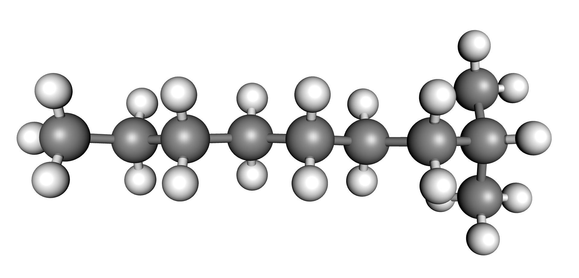 | 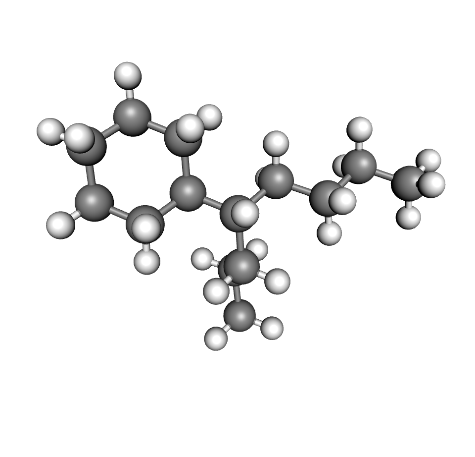 |  |
Transformer oil is considered naphthenic or paraffinic depending on which structure is more prevalent for a particular oil. In general, if the oil contains between 56 to 65% of carbon bonded paraffin the oil is considered paraffinic. If it contains between 42 and 50% of carbon bonded paraffin, the oil is considered naphthenic. Oils in between these percentages are considered intermediate (3). The content of these compounds influence the various properties of the oil including, oxidation stability, viscosity, temperature stability, gas absorption, dielectric properties, etc.
The properties that new oils have to meet are established in either national or international standards (4).
The transformer as a chemical reactor
In the context of Dissolved Gas Analysis (DGA), the transformer can be thought of as a chemical reactor.
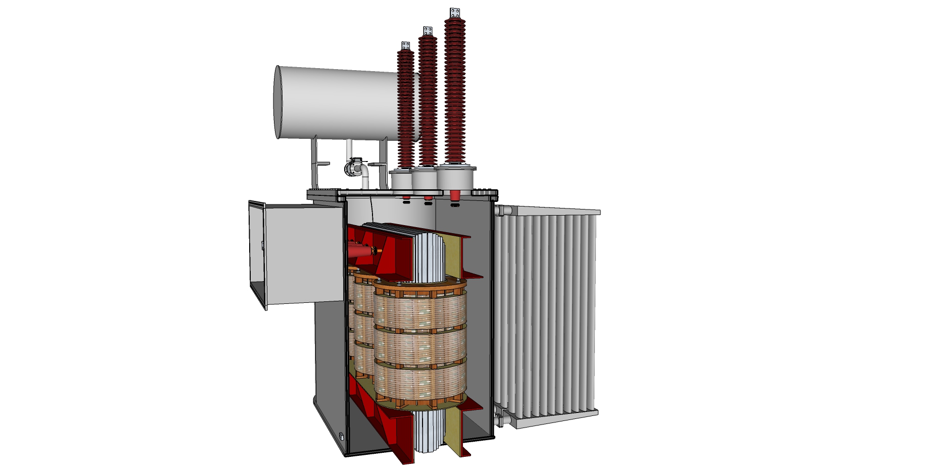 Internal view of a typical power transformer
Inside the tank there are numerous organic and inorganic compounds that can engage in chemical reactions. Copper from the windings and steel from the core and clamping structures. Hydrocarbons from the insulating oil. Cellulose from the paper, insulating boards and blocks.
Also, there are sources of energy in the form of the losses generated during normal operation as well as the energy contributed by abnormal conditions and faults.
This mix of energy and reactive compounds can be visualised as a chemical reactor where the energy source drives the various reactive materials into decomposing and recombining to form new chemical by-products. Since these by-products are measurable and quantifiable we can aim to find useful correlations between the energy injected into the system and the chemical behaviour of the components that make it up.
These correlations represent a powerful tool in the assessment of the condition of the transformer. To diagnose the condition of the transformer we are interested in two main components of the insulation system, the liquid and the solid insulation. The liquid insulation comprised by the oil and the solid comprised by paper and pressboard.
Each of these elements contribute in very specific ways towards the formation of gases. We will see how in the next section.
Gas production mechanisms
As mentioned above, the oil is comprised of hydrocarbon molecules. As early as 1919 (5), researchers noticed that abnormal conditions, such as disruptive discharges under the oil, produced certain amounts of hydrocarbon by-products.
The heat produced by the losses and certain types of failure modes as well as the energy dissipated by electrical discharges contribute to the breakdown of the oil molecules. The main by-products of these process are shown in the figures below.
| Hydrogen | Methane | Ethane | Ethylene | Acetylene |
|---|---|---|---|---|
 | 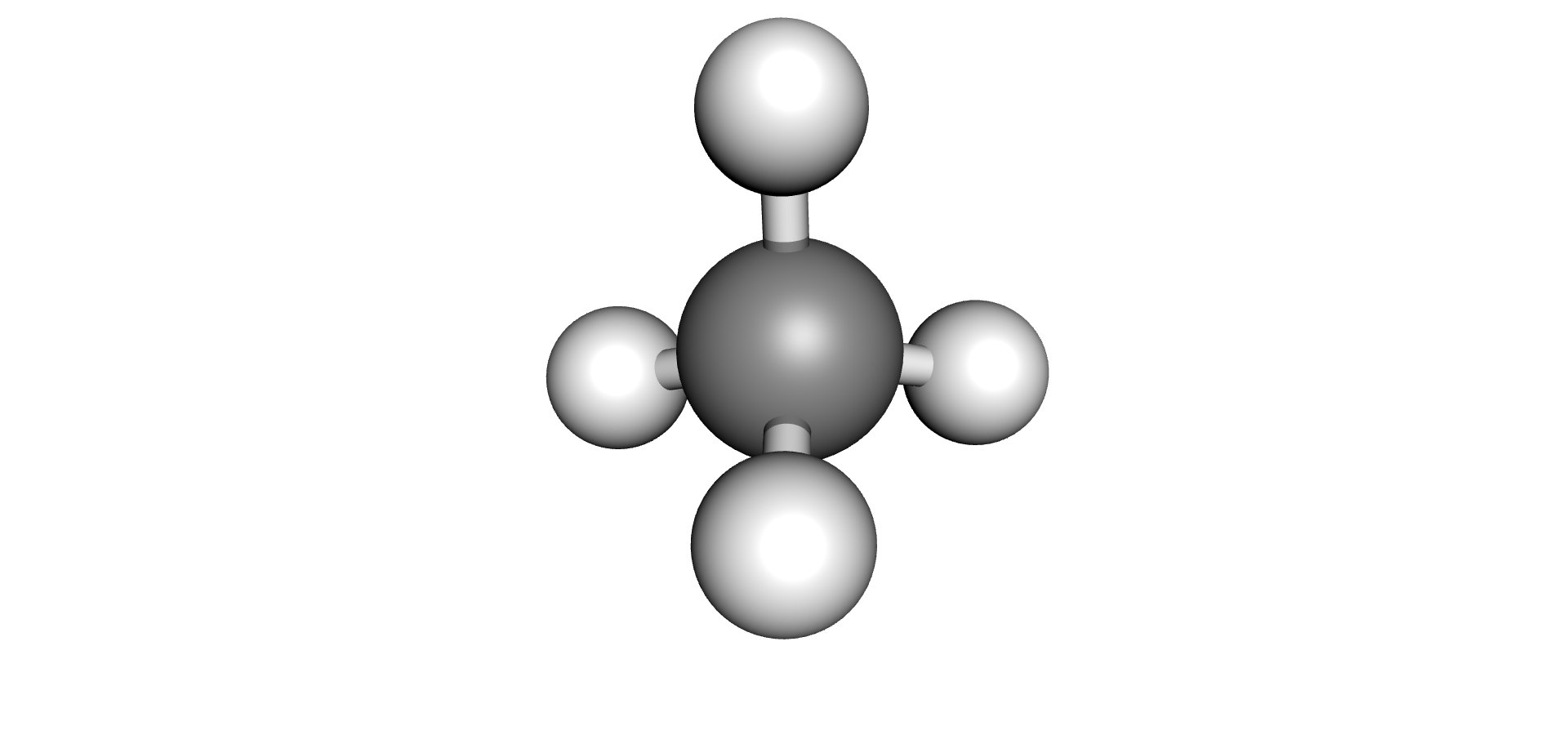 | 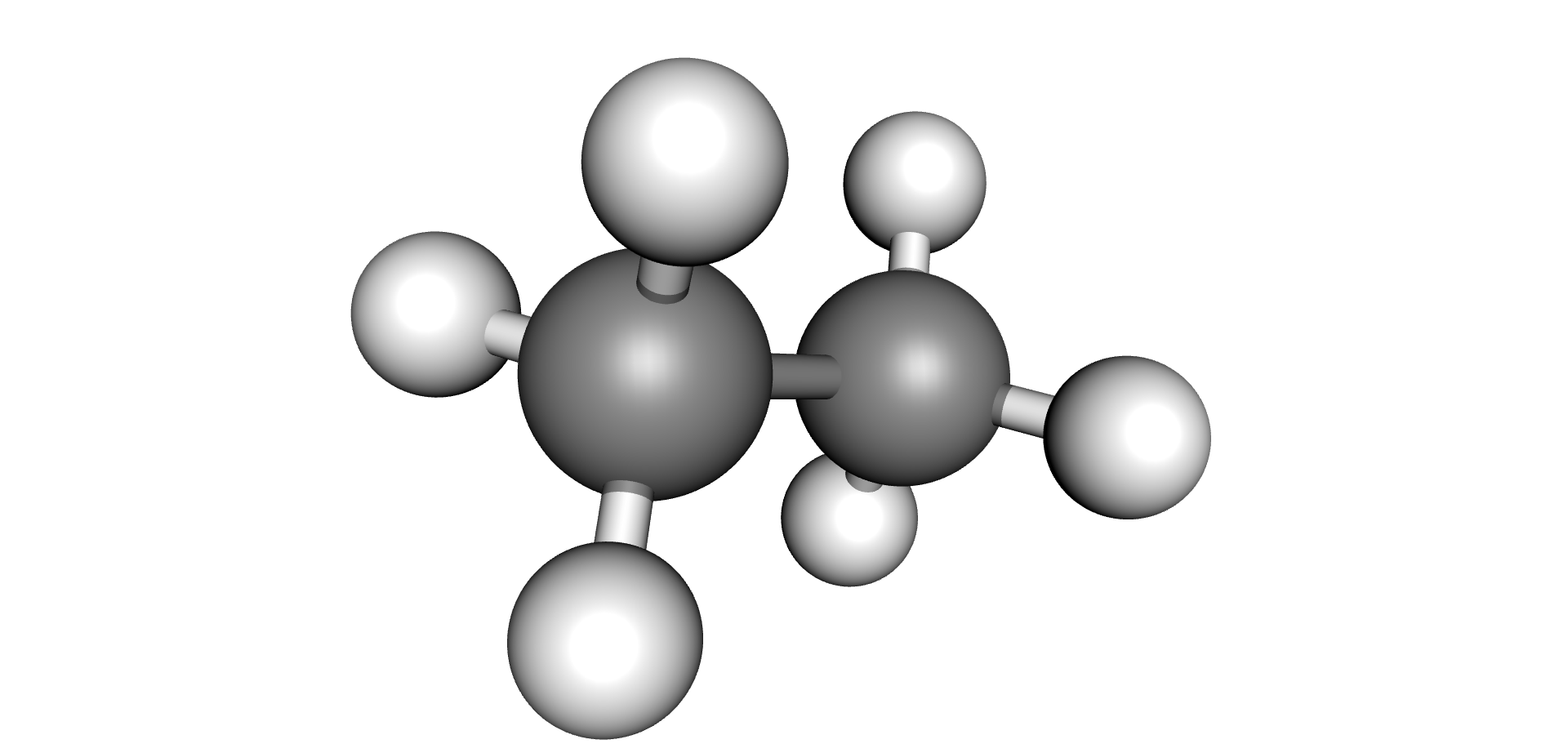 | 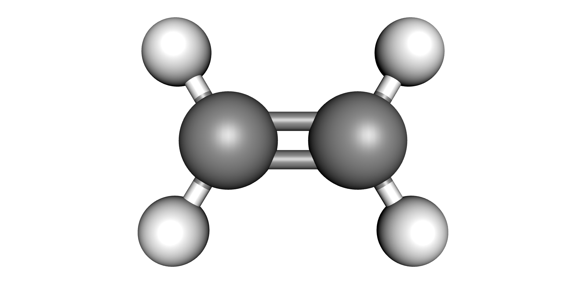 | 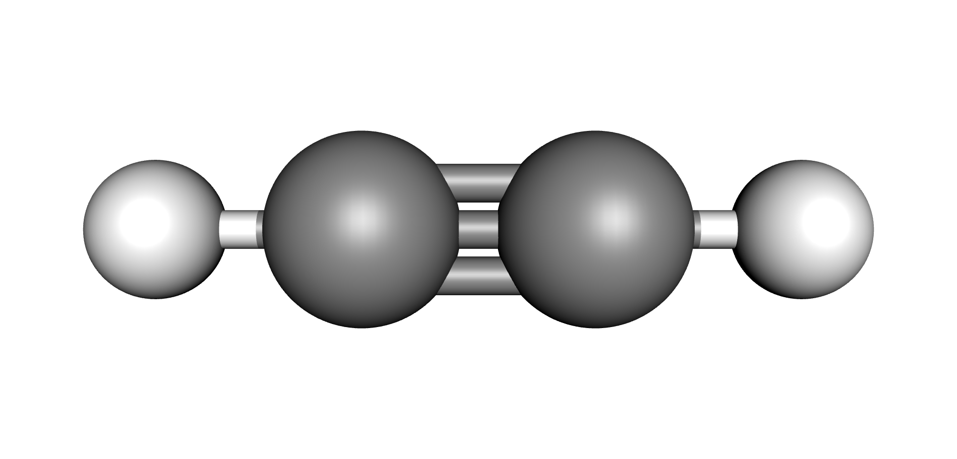 |
Each type of chemical bond requires a different level of energy to break or join (6) (7). The energy required to break or make single bonds of Hydrogen-Hydrogen atoms present in the Hydrogen molecule is about half of the energy required to form the triple Carbon-Carbon bond present on the Acetylene molecule. As these by-products are produced, they remain dissolved in the oil up to their solubility limits, after which they would evolve as free gases (bubbles).
The fact that these gases are produced at distinct energy levels has been crucial to our ability to infer the type and intensity of the mechanisms that produce them. Efforts to use this behaviour for diagnosis purposes were underway in the early 1970’s (8).
By studying the amount, proportion and evolution rates of these various gases dissolved in the transformer oil, engineers have been able to correlate them to known failure modes and their severity levels.
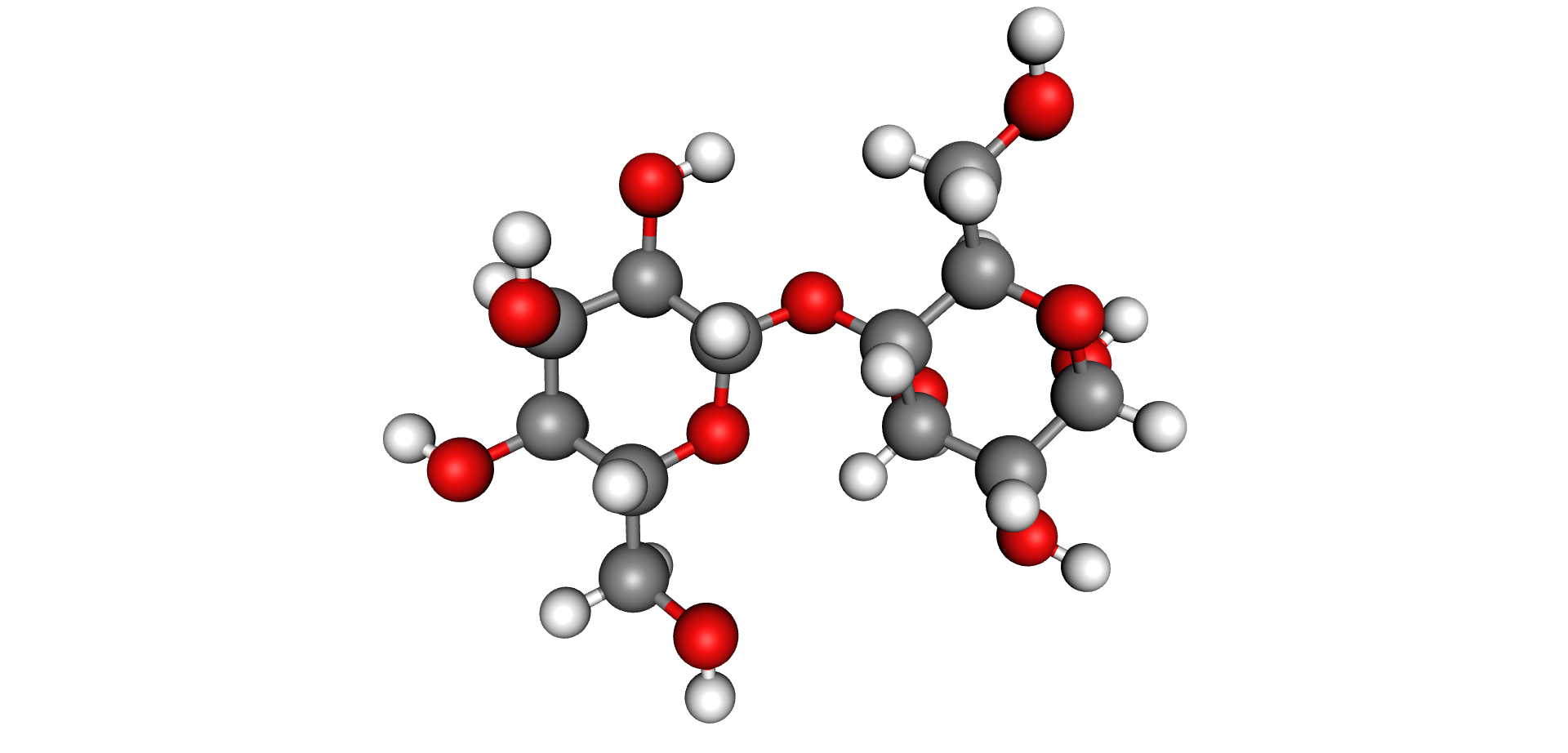 Cellulose Molecule
These are not the only gases or by-products produced by the chemical reactions inside the transformer. As we pointed out before, other than the hydrocarbons present in the oil, there are additional materials present in the transformer that also interact during these chemical reactions.
One of the most important components of the insulation system, aside from the oil, is the solid insulation system. This insulation, comprised of paper, pressboard and other solid materials is made up of cellulose fibres. Cellulose is an organic compound made up of long chains of the same repeating building block as depicted in the figure below.
The red atoms in the Cellulose Molecule image above are Oxygen atoms. The same energy that causes the oil to breakdown will have a similar effect on the paper. At a molecular level, all cellulosic materials are made up of long chains called polymers.
Another contributor of Oxygen is water. A brand new transformer that has been properly manufactured and assembled will tend to have less than 0.5% of residual moisture per dry-weight of insulation throughout the insulation system after it is commissioned. However, throughout the life of a transformer it would not be uncommon that additional water enters the system via improperly maintained breathing systems or oil leaks.
Finally, in some cases, such as in free-breathing transformers, Oxygen enters via the normal “breathing” process of the oil expanding and contracting due to temperature changes.
For all these Oxygen containing compounds, increases in temperature, either through normal losses or during abnormal events or faults, cause the C-O molecular bonds to break up which releases Oxygen, Carbon and Hydrogen into the oil. These elements recombine to form Carbon Monoxide (CO), Carbon Dioxide (CO2), Water (H2O) and a range of compounds collectively known as Furans. It is worth pointing out that neither Water nor Furans are part of a gas analysis and they are measured using other methodologies beyond the scope of this chapter.
| Water | Carbon Monoxide | Carbon Dioxide | Furfural (2-FAL) Furan |
|---|---|---|---|
 | 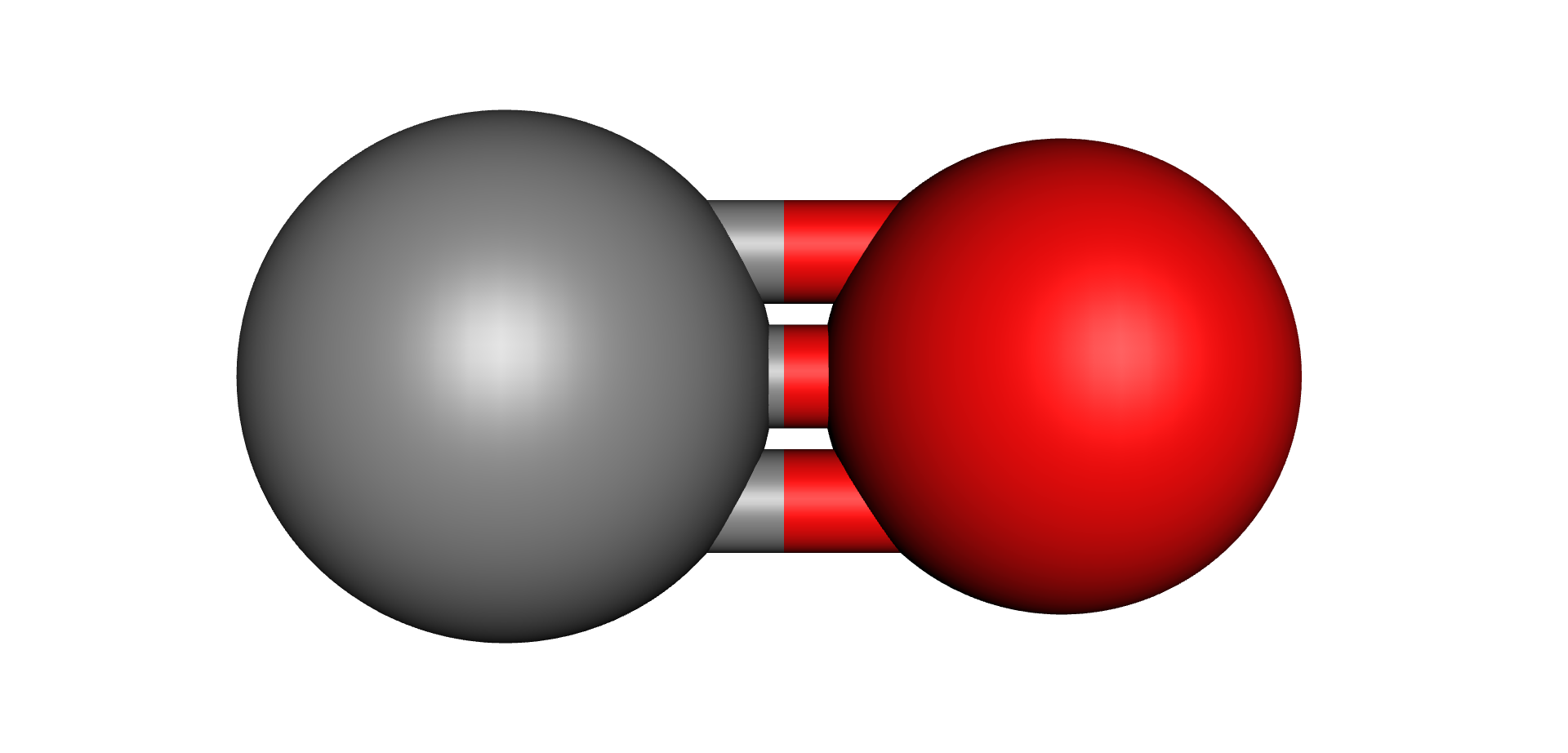 | 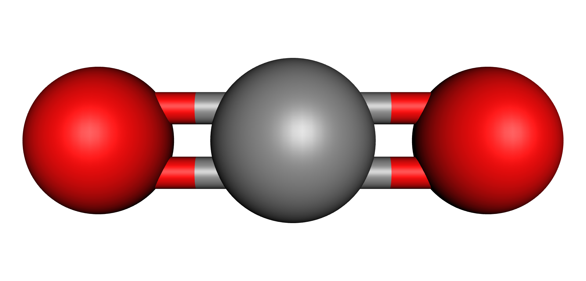 |  |
In more recent years (9), a gas production mechanism known as “Stray Gassing” has been characterised. Stray gassing is recognised as the production of gases within a temperature range of 90°C and 200°C. Experiments (9) have shown that this mechanism mostly produces Hydrogen (H2) and Methane (CH4). The amount of these gases produced has a correlation with the specific brand and type of oil used in each particular transformer.
While more specific mechanism of gas production are being researched (10) the above mechanisms provide a good overall picture of how oil, paper, water, oxygen and energy interact to produce them.
In summary, we can see that these gas production mechanisms hold a correlation to the chemical elements present inside the transformer and the levels of energy available to enable these chemical reactions to occur. As we will see in the next sections, the transformer engineering community has developed several interpretation techniques that take advantage of this behaviour.